@MrBeaver wrote:
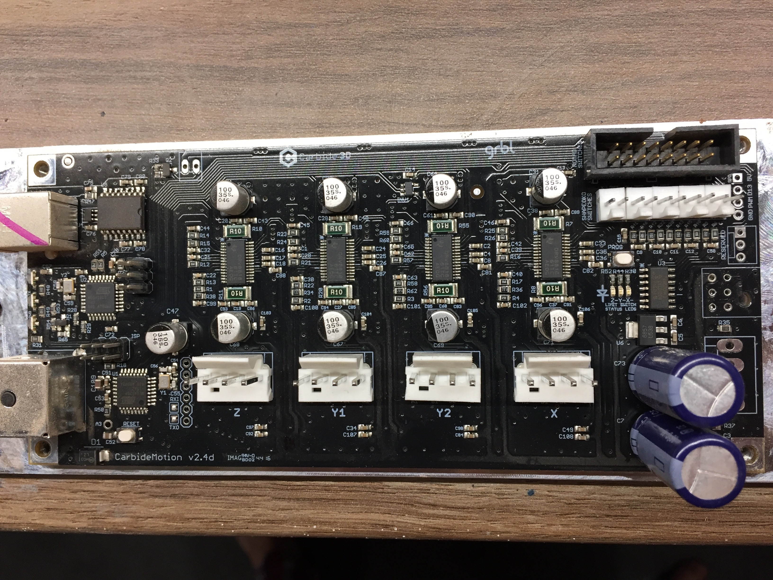
I was wondering - is there a diagram for the 2.4 board?
I'm keen to get a proper diagram for this version. I have the older 2.1 version that floats around but it's missing the important Nomad Connector. The reasoning behind this is that I want to tap into some pins - but I'd have to manually add them - something I'd rather not do if I can help it.
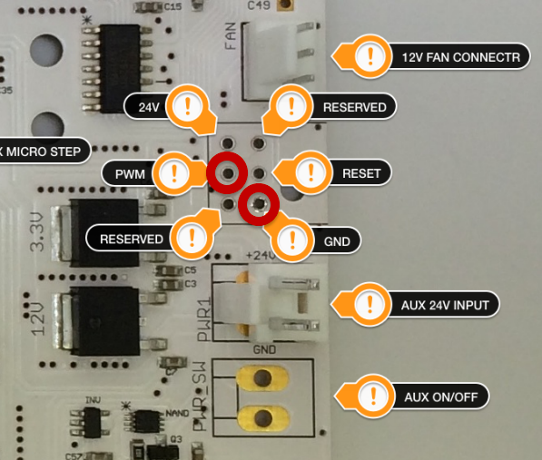
On the top RHS there is a 5V and ground output and PWM (I believe for Laser control) There is also something called D13 - spindle enable.
Now just below these 4 pins there is also the set of 6 pins and then 2 sets of two or 4 pins which are likely in the same configuration as the earlier board:
However and my main point - at the top right of the board there is what I believe to be the Nomad controller plug (big black one) - I would put a couple of quid on all these pins being in that connector - and if I could tap into a couple of them I can save a bunch of time soldiering on pins - it would also allow me and others to quickly attach say a Laser accessory or Super PiD etc?
Thoughts guys?

Posts: 1
Participants: 1